BACKLIGHTING WITH JULIA-A
Find all related products
For help with an application simulation using our optics, or to make a request about what application you want us to cover next, contact Tech support
JULIA-A is an extremely wide batwing lens that is designed to be used in backlight projects. The extra wide batwing design ensures good performance against flat surfaces. Uniformity of JULIA-A arrays can be well over 90%. JULIA-A has highest intensity spikes around 75-80deg depending on the LED model.
Data measured with 4 LEDs in square arrangement with 100 mm spacing through white semi-transparent PC sheet.
Each LED has its own light output that varies even between same LED types inside same bin. This kind of variance might have some negative effect on the uniformity of the system. The type of the illuminated semi-transparent front panel can also have negative or positive effect on the uniformity.

Data measured with 4 LEDs in square arrangement with 100 mm spacing through white semi-transparent PC sheet.
| LED type | Optimal height | min/avg | min/max |
|---|---|---|---|
| XP-E | ca.50 mm | 0.97 | 0.94 |
| XP-G | ca.50 mm | 0.96 | 0.93 |
| Rebel | ca.40 mm | 0.96 | 0.91 |
| Rebel ES | ca.50 mm | 0.94 | 0.90 |
| NVSx19 | ca.40 mm | 0.94 | 0.87 |
SIMULATIONS
Back lighting setups can’t usually be simulated with light simulation software like Dialux. Distances on the backlighting setups are usually few centimeters so accurate simulations require near field ray tracing. Light transmission and diffusive properties of the front panel needs to be taken into account for accurate simulation.LED ARRAY ARRANGEMENTS
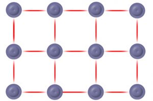
Square arrangement
Square arrangement is probably the most common way to build the LED array. Lenses like Julia-A usually have round light distribution pattern so the performance is not optimal in square arrays. Julia-A still manages to have excellent performance when used in square arrangements.
Equilateral triangle arrangement
Equilateral triangle arrangement is more suited for lenses with round light distribution. LEDs are spaced more evenly than in standard square arrangement. Light patterns of each LED overlap more evenly which leads to better uniformity in many cases. The information contained herein is the property of LEDiL Oy, Joensuunkatu 7, FI-24100 SALO, Finland and is subject to change without notice. Please visit lediloptics.cn for additional information, such as the latest photometric files, 3D mechanical models, and application notes relating to handling, gluing and taping.